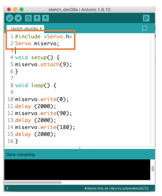
Unlike their universal counterparts, which can only rotate from 0 to 180 and have no speed control other than position control, continuous rotation servos allow us to control the rotational direction and set the speed as well. sleep ( 0.05 ) for x in range ( 180, 0, - 1 ): print x, "degree" servo. 360 degree servo motors (also known as continuous rotation servo motors) are a special version of servo motors that can rotate continuously. argv )) while True : for x in range ( 0, 180 ): print x, "degree" servo. exit ( 1 ) servo = GroveServo ( int ( sys. Myservo.attach(5) // attaches the servo on pin 5 to the servo objectįor (pos = 0 pos = 0 pos -= 1) servo_channel'. Int pos = 0 // variable to store the servo position twelve servo objects can be created on most boards Servo myservo // create servo object to control a servo
#PROGRAMA SERVO MOTOR ARDUINO CODE#
This example code is in the public domain. Open the code directly by the path: File -> Examples ->Servo->Sweep.Let's sweep the shaft of a servo back and forth across 180 degrees by using Adruino Servo Library.Connect the module to D5 port of Base Shield.

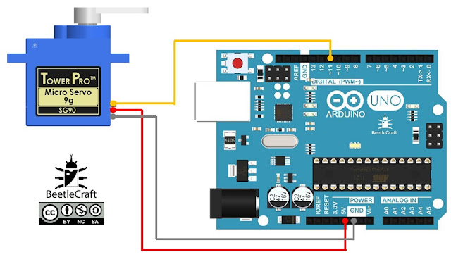
But don't forget to change the port number in the definition of the demo code at the same time. We can change to the digital port as we like. The signal pin is typically yellow, orange or white and should be connected to D5 on the Arduino board. The ground wire is typically black or brown and should be connected to a ground pin on the Arduino board. The power wire is typically red, and should be connected to the 5V pin on the Arduino/Seeeduino board. The Servo has three wires: power, ground, and signal. First of all, we need to prepare the below stuffs: Seeeduino V4 Here we will show you how this Grove - Servo works via a simple demo.
#PROGRAMA SERVO MOTOR ARDUINO SOFTWARE#
Hence, users have to write their own software library. It is not possible to provide software library / demo code for all possible MCU platforms. We only provide software library or code examples for Arduino platform in most cases. You support me on patreon for more videos.The platforms mentioned above as supported is/are an indication of the module's software or theoritical compatibility.
/esquema-arduino-servo.jpg)
Then, using the analog write function, we send the value stored in variable data, the pwm pin, which is deep in number 5 and its name is MBM. Then using the map function we limit the maximum value to 255 and store the Maebh value and data. Is the input the pin, number or pin name and the status which can be input on output, his micro vibration, motor? Is the output device so that’s? Why we set it to output? While the variable resistor is set to input then starts the vital function? Data is equal to analog feed, avi resistor, reads the variable, resistor and store the value and variable data. Pin mode is a built in function, and it takes two arguments. White means that these functions are not returning any value, while the empty parenthesis means that these functions are not taking any arguments, is the input. Every Arduino and mega program has at least 2 functions, which are the white set up and by loop functions. The variable resistor value will be stored and data as no more friends. A variable resistor is connected with the analog pin a 1 of the Arduino integer data is equal to 0. You can use any pwm pin of the arduino integer v resistor is equal to a 1. Motor is connected with pin number 5, which is the pwm pin of the arduino. Motor programming is really simple indeed or MDM is equal to 5 micro vibration. Motor now let’s discuss the Arduino programming, the micro vibration. You now we will use this variable resistor to control the vibration of the micro vibration. Pin even of the Arduino now connect the gray wire with the ground, connect the red wire with the 5 volt Kaneda red wire of the micro vibration motor with the number 5, which is the pwm pin of the arduino, connect the blue wire with the Audrina’s ground. The red wire is de positive and the blue wire is the ground connecting middle leg of the variable resistor, with analog. As you can see, the two wires are soldered and now it can be easily interfaced with the Arduino. So I decided to fix the vibration motor on a small, PCB board you now I will solder to jump of ice. As you can see, the vibration motor has small 10 wires into the which it’s really hard to interfaced with the Arduino. The rated voltage is 3.7 volts and current is point zero, seven amps, which is equal to 70 milliamps. The working voltage of the micro vibration motor is two to five volts. As you can see, it has two wires red and Blake red is the positive wire. These components can be purchased from Amazon, the components purchase links are given in the description. As you can see, I have already soldered three jumper wires so that it can be easily interfaced with the Arduino. Audrina number two micro vibration motor number, three, a variable resistor. Let’S get started, the components needed for this project are number one.


The vibration can be increased and decreased without any further delay.


 0 kommentar(er)
